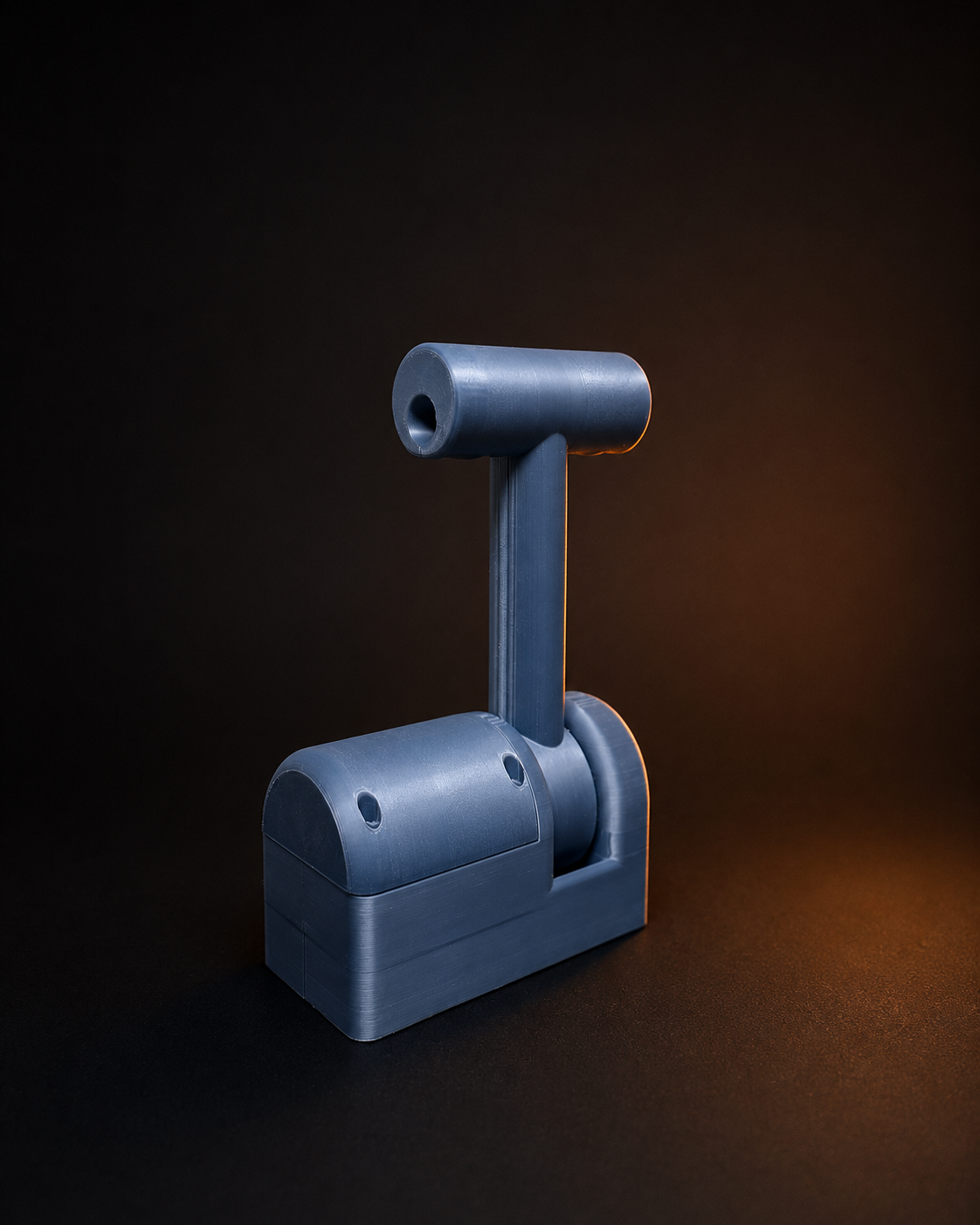
A custom-built throttle interface developed for a sailboat restoration project, designed to replace a mechanical cable system with an electronic control concept.
Introduction
Not every engineering problem calls for an off-the-shelf solution. When a client restoring a sailboat needed to replace an aging mechanical throttle cable system with a modern electronic alternative, the requirement was clear: design and build a custom-built control interface that could sit in place of the original unit, behave intuitively, and integrate with a relay-driven servo actuation system. The result is a fly-by-wire control interface developed around a specific installation, a specific boat, and a specific restoration goal.
Project Context
The client was in the process of restoring a sailboat and wanted to remove the original mechanical engine throttle cables entirely. In their place, an electronic control concept would be introduced — one capable of reading lever position, interpreting that position into gear and throttle commands, and actuating the engine controls via servo motors rather than physical cables.
The brief was not to develop a universal marine product. It was to build one functional assembly that would fit the existing console space, replicate the feel of the original control, and serve a single, well-defined application.
Control Logic
The throttle operates around a central neutral position. Moving the lever in either direction follows a defined engagement sequence:
- Neutral: Lever at centre position. No gear engaged.
- Forward gear engagement: Approximately 10 degrees of lever travel triggers forward gear.
- Forward throttle range: The remaining approximately 80 degrees of travel modulate engine throttle in the forward direction.
- Reverse gear engagement: The same logic is mirrored in the opposite direction — roughly 10 degrees triggers reverse gear.
- Reverse throttle range: The remaining approximately 80 degrees control throttle in reverse.
Additionally, the lever grip incorporates a two-way momentary push button, integrated within the handle itself, allowing for auxiliary input without releasing the throttle.
Design Constraints
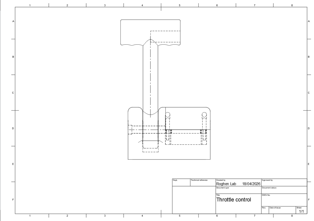
The most significant design constraint was intent: this was a replacement component, not a redesign. The original throttle occupied a defined space on the console and had an established form the operator was familiar with. Departing radically from that form would have created unnecessary retraining and potential fitment issues.
As a result, the CAD-developed enclosure follows closely the proportions and general silhouette of the original unit. Some lines and surfaces are deliberately simple — not because of a lack of design consideration, but because fidelity to the original form was a requirement. The goal was a familiar interface and footprint, not a showcase of aesthetic freedom.
CAD Development
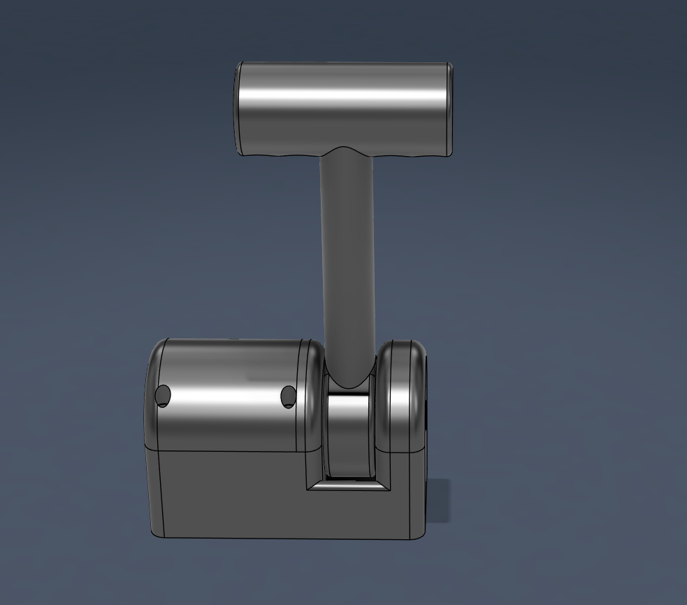
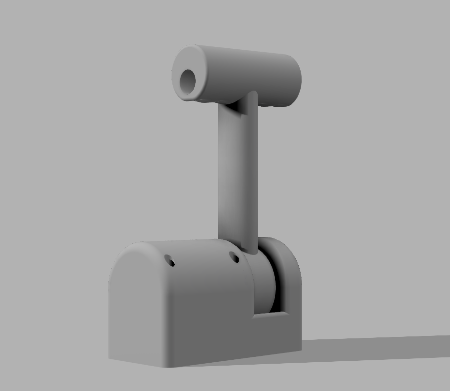
The CAD work was carried out in Fusion 360. The primary focus of the modelling effort was the housing and mechanical layout: defining the enclosure geometry, establishing the lever pivot geometry, allocating internal space for electronics, and ensuring that all components could be assembled and accessed if needed.
Electronics were accounted for in terms of volume and placement — the Arduino, wiring runs, and connector access points all informed the internal structure — but the housing itself was the main developed artefact. The mechanical packaging of the electronics into a coherent physical enclosure was the primary design challenge.
Iteration Process
The development followed two distinct versions:
Version 1 was focused on validation. The printed part was used to assess the overall footprint, confirm dimensional fit against the original mounting area, and identify areas where the internal volume was insufficient or the geometry needed adjustment. No attempt was made to refine surface quality or internal organisation at this stage.
Version 2 addressed the findings from the first iteration. Internal routing and component placement were improved, the external geometry was refined, and the overall layout brought closer to the intended final configuration. The printed housing from this version reflects the current state of the project.
It should be noted that the printed part at this stage does not yet include the final aperture for the potentiometer on the throttle shaft — this detail remains to be incorporated in a subsequent update.
Material Selection
For a functional custom enclosure deployed in a marine-adjacent environment, material choice is a practical decision, not an aesthetic one.
PLA, while common and easy to print, is not well suited to outdoor or exposed applications. It has limited UV resistance and relatively low thermal stability, making it a poor candidate for any housing that will experience sunlight, heat variation, or moisture over time.
ASA (Acrylonitrile Styrene Acrylate) is a more appropriate candidate for this type of application. It offers better UV stability than PLA, improved weather resistance, and higher thermal tolerance — characteristics that matter in a cockpit or helm environment where temperatures can fluctuate and direct sunlight exposure is expected.
It is important to note that no specific marine certification or waterproofing claim is made here. ASA’s properties make it a more suitable choice than standard PLA for this context, but formal marine qualification would require dedicated testing and validation beyond the scope of this project.
Electronic Integration Concept
The electronic architecture is designed around simplicity and directness. The signal path follows a clear sequence:
Lever movement → Potentiometer signal → Arduino processing → PWM output → Servo motor actuation
In practice:
- A potentiometer is mounted to the throttle shaft, producing an analogue signal proportional to lever angle.
- An Arduino housed within the throttle enclosure reads that signal continuously and interprets it according to the defined control logic — neutral band, gear engagement threshold, and throttle range.
- The Arduino outputs PWM signals that directly drive the servo motors, commanding position proportional to the interpreted throttle input.
- High-torque 90 kg metal gear servo motors on the engine side receive those PWM signals and physically actuate the engine controls, replacing what the original mechanical cables would have done.
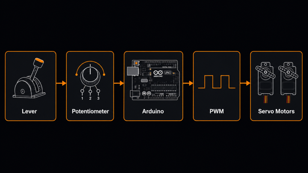
The concept keeps the logic centrally contained within the throttle housing. The servo motors act as the mechanical output stage at the engine, entirely separated from the operator’s input device.
Physical Validation

The printed housing from the second iteration demonstrates the core physical intent of the project: a custom 3D printed housing that fits within the original console footprint, accepts the lever assembly and internal electronics, and presents a familiar control form to the operator. Physical validation at this stage confirmed the overall geometry, the lever pivot behaviour, and the internal volume available for component integration.
Outcome
The project produced a custom fly-by-wire control interface designed specifically for one boat and one restoration brief. It is not a product. It is not intended for replication or adaptation beyond its target application. It is a custom-built physical solution developed through CAD modelling, iterative prototyping, and considered mechanical packaging — with a defined electronic control concept ready to be realised once installation progresses.
The two printed iterations validated the design approach. The electronic architecture is established. The remaining steps potentiometer aperture, final assembly, and servo integration — are defined and achievable within the existing design framework.
Custom Physical Solutions for Technical Problems
This project is representative of the type of work undertaken at Roghen Lab: a specific technical requirement, translated into a physical object through CAD development, iterative validation, and application-specific thinking. There is no catalogue for what a client restoring a sailboat needs. There is a problem, a set of constraints, and a process of turning those into something that can be held, installed, and used.